Segmentation Techniques for Complex Geometry

Complex geometry demands structure before it can be meshed effectively. This article introduces the key techniques used to segment surfaces into meaningful regions, explains the geometric signals behind them, and illustrates how segmentation drives mesh quality. It’s a practical, visual guide to one of the most important steps in modern geometry processing.

Download PDF 
segmentation_concept

The Importance of Segmentation

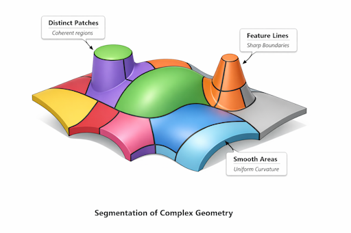
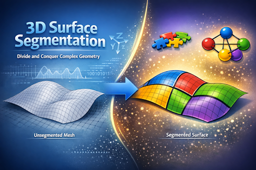
Within computational geometry and mesh generation, segmentation refers to the division of a surface into coherent regions, each exhibiting consistent geometric properties and meshing requirements. These regions, termed segments, are fundamental for patch-based meshing, adaptive refinement, and solver stability.

Segmentation represents more than a preprocessing step; it is a structural transformation that translates raw geometry into a meshable domain by:

  • Uncovering intrinsic structure such as curvature zones, sharp transitions, and functional boundaries.
  • Directing element alignment to ensure mesh elements follow the geometric flow.
  • Managing refinement by facilitating localized mesh density where necessary.
  • Enhancing solver performance through reduced skewness, improved aspect ratios, and minimized Jacobian inversion issues.

Absent robust segmentation, meshing algorithms may apply uniform strategies to heterogeneous geometry, resulting in distorted elements, compromised boundaries, and unreliable simulations. Segmentation enables geometry to become suitable for meshing.

Definition of a Segment

A segment refers to a contiguous area of a surface characterized by consistently uniform geometric properties. From a differential-geometric perspective, a segment constitutes a portion of the surface where factors such as curvature, normal variation, and feature structure transition smoothly, enabling the region to be regarded as a singular meshing entity. Segments are defined by the inherent qualities of the surface rather than arbitrary delineations.

A well-defined segment typically meets the following criteria:

  • Geometric coherence — Smooth variation in surface normals, stable principal curvature directions, and predictable curvature magnitudes support a mesh with consistent orientation and sizing.
  • Feature homogeneity — The segment avoids crossing sharp edges, ridges, valleys, or other feature lines, which serve as natural boundaries due to their discontinuities or extrema in differential properties.
  • Meshing compatibility — The segment supports a single meshing approach (structured, semi-structured, or unstructured) without incurring excessive distortion, often serving as the practical constraint for adequacy.

Mathematically, segmentation can be interpreted as a classification problem on the surface manifold. Each point carries geometric descriptors, including:

  • Normal vector \( \mathbf{n}(p) \)
  • Principal curvatures \( k_1(p), k_2(p) \)
  • Principal directions \( \mathbf{e}_1(p), \mathbf{e}_2(p) \)
  • Curvature derivatives \( \nabla k_1, \nabla k_2 \)
  • Surface connectivity and topology

Segments correspond to regions where these descriptors exhibit smooth, predictable variation. Discontinuities, abrupt gradients, or topological changes prompt division into separate segments.

In engineering contexts, segments reflect meaningful functional regions: planar faces, cylindrical patches, fillets, freeform blends, or organic curvature zones. Identifying these regions is vital as each necessitates unique meshing behavior—such as alignment along curvature flow, refinement near transitions, or structured grids on developable surfaces.

Thus, segmentation comprises both geometric and functional decomposition, elucidating the construction, behavior, and meshing requirements of the surface.

Segment Definition

Signals Guiding Segmentation

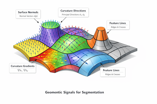
Segmentation fundamentally involves processing signals on a curved manifold. Each surface point possesses differential-geometric information, and segmentation results from analyzing signal variations across the surface. The objective is to delineate boundaries where surface behavior alters abruptly or meaningfully, warranting distinct meshing strategies.

Key signals include:

Geometric Signals Map

Surface Normals

The surface normal \( \mathbf{n}(p) \) provides immediate insight into local orientation. Segmentation boundaries typically occur where the normal field demonstrates:

  • Discontinuities (sharp edges)
  • High gradients (creases or tight blends)
  • Directional reversals (transitions between concave and convex regions)

The magnitude of the normal gradient ∇n is a strong indicator of segmentation boundaries, notably in CAD-like surfaces.

Principal Curvature Magnitudes

Principal curvatures \( k_1(p) \) and \( k_2(p) \) capture surface bending characteristics. Their distribution identifies:

  • Flat or developable areas (low curvature)
  • Highly curved fillets or blends (high curvature)
  • Ridges and valleys (curvature extrema along principal directions)

Segmentation aligns with regions experiencing significant curvature magnitude changes or threshold crossings.

Principal Curvature Directions

Principal directions \( e_1(p) \) and \( e_2(p) \) define bending orientation, forming a vector field over the surface. Boundaries arise when:

  • The direction field rotates sharply
  • Instability or noise emerges in the field
  • Dominant curvature direction switches

Such transitions indicate that consistent meshing orientation cannot persist throughout the segment.

Curvature Derivatives

Derivatives \( \nabla k_1 \) and \( \nabla k_2 \) quantify how curvature evolves across the surface. They are pivotal for identifying:

  • Ridges (maxima of \( k_1 \) along \( e_1 \))
  • Valleys (minima of \( k_1 \) along \( e_1 \))
  • Blend transitions (rapid yet smooth curvature changes)

These derivatives underpin feature lines serving as segmentation boundaries.

Surface Boundaries and Topology

Segmentation must accommodate the surface’s topology, including:

  • Open boundaries
  • Holes and handles
  • Junctions of multiple patches

These constraints naturally define the limits of the surface manifold.

Connectivity and Mesh Structure

Mesh representations, even for CAD surfaces, supply additional cues:

  • Irregular valence nodes
  • Non-uniform sampling
  • Connectivity alterations

Such indicators often correlate with geometric transitions, affirming segmentation decisions.

Interaction of Signals

Segmentation rarely hinges on a single signal; boundaries manifest where multiple signals converge:

  • A sharp edge results from both normal discontinuity and a curvature jump.
  • A ridge combines an extremum in curvature derivative and stable principal direction.
  • A blend transition features smooth curvature but high curvature gradient.

This multi-signal concurrence establishes segmentation robustness and scientific validity.

Segmentation Strategies

Segmentation encompasses a range of algorithmic methodologies, each grounded in distinct geometric signals and mathematical foundations. There is no universally optimal approach; instead, every method reveals a particular facet of a surface's structural characteristics. In practice, advanced segmentation systems integrate several of these techniques to achieve an optimal balance between precision, clarity, and computational performance.

Below are the primary categories of segmentation techniques.

Strategy Comparison Diagram

Feature-Line-Driven Segmentation

This method employs detected feature lines - including sharp edges, ridges, valleys, creases, and blend transitions - to define explicit segment boundaries. It is highly intuitive and aligns closely with engineering conventions, as feature lines correlate with significant geometric phenomena.

Feature-line segmentation proves effective when:

  • The geometry exhibits CAD-like properties with distinct functional regions.
  • Feature detection is consistent and reliable.
  • The objective is to generate clear and interpretable patches.

Mathematically, feature lines indicate discontinuities or extrema in:

  • The normal field \( n(p) \)
  • Principal curvature \( k_1,k_2 \)
  • Curvature derivatives \( \nabla k_1,\nabla k_2 \)

Such discontinuities demarcate natural boundaries where differential properties experience abrupt changes. Consequently, segmentation becomes a matter of tracing these curves and partitioning the surface accordingly.

The primary limitation lies in sensitivity: unreliable feature detection results in segmentation errors.

Curvature-Based Segmentation

Curvature-based segmentation divides the surface based on curvature magnitude and variation. Rather than relying solely on discrete feature lines, it assesses the continuous curvature field to distinguish regions exhibiting similar bending behaviors.

This approach is particularly suitable for:

  • Organic forms
  • Scanned or reconstructed surfaces
  • Freeform geometries without pronounced edges

Common signals include:

  • Regions where \( k_1 \) and \( k_2 \) remain relatively constant
  • Areas with significant curvature gradients (blend transitions)
  • Changes in curvature sign (convex versus concave)

Typically, clustering or region-growing algorithms are applied to curvature descriptors. The main challenge involves scale sensitivity: curvature responds strongly to noise and sampling density, necessitating smoothing and multi-scale analysis.

Spectral Segmentation

Spectral techniques conceptualize the surface as a manifold, analyzing its global characteristics via eigenfunctions of the Laplace–Beltrami operator. These eigenfunctions encapsulate intrinsic geometric information and effectively segment the surface into coherent regions.

Spectral segmentation offers considerable advantages:

  • Captures global shape characteristics beyond local curvature
  • Demonstrates resilience to noise and irregular sampling
  • Reveals segmentation boundaries that may not be apparent from local geometric cues

The Laplace-Beltrami eigenfunctions \( \phi_i \) serve as smooth scalar fields across the surface. Level sets or clusters formed within this space delineate segmentation regions.

However, spectral methods often present interpretability challenges; resulting segments may diverge from engineering expectations unless supplemented by feature-based signals.

Graph-Based Segmentation

Graph-based methods model the mesh as a weighted graph, utilizing edges that convey geometric information such as:

  • Normal differences
  • Curvature differences
  • Dihedral angles
  • Geodesic distances

Segmentation is accomplished through various graph algorithms including:

  • Region growing
  • Minimum cuts
  • Clustering (e.g., k-means, spectral clustering)
  • Community detection

These methods are adaptable and capable of integrating multiple geometric signals concurrently. They are especially beneficial for:

  • Noisy meshes
  • Mixed geometry (CAD combined with organic structures)
  • Large, intricate models

The principal difficulty is determining appropriate weights and thresholds to produce meaningful segmentation results.

Hybrid Segmentation

Hybrid approaches synthesize feature lines, curvature analytics, spectral data, and graph-based reasoning. This methodology delivers robust solutions for real-world geometries, where individual signals may lack reliability.

A standard hybrid workflow might involve:

  • Employing feature lines as definitive boundaries
  • Conducting curvature-based clustering within each region
  • Leveraging spectral data to discern overall structure
  • Applying graph refinement to enhance boundary quality

Hybrid segmentation achieves:

  • Interpretability (via feature lines)
  • Smoothness (through curvature fields)
  • Global coherence (from spectral techniques)
  • Robustness (via graph algorithms)

This integrative direction represents the prevailing trend among contemporary meshing systems.

Hybrid Segmentation Pipeline

Visualizing Segmentation

Segmentation constitutes a geometric classification challenge whose effectiveness is closely tied to robust visualization strategies. Engineers and researchers depend on visual representations to verify segmentation boundaries, interpret geometric characteristics, and evaluate whether the resulting partitions will facilitate high-quality meshing. Carefully implemented visualization serves as a vital link between abstract differential-geometric signals and practical decisions regarding meshing.

Visualization methodologies are classified into several complementary types, each illuminating distinct facets of the segmentation process.

Visualizing Segmentation

Color-Coded Segments

A widely used technique involves assigning a unique color to each segment, offering immediate insight into surface partitioning and confirming alignment with geometric expectations. Color-coding assists in identifying issues such as:

  • Over-segmentation (excessively fragmented patches)
  • Under-segmentation (extensive patches with mixed geometric properties)
  • Boundary misalignment (segments intersecting feature lines or transitions in curvature)
  • Topological discrepancies (such as holes or disconnected areas)

This approach is particularly effective for presenting results to audiences without technical expertise, as it offers a clear and accessible overview.

Feature Lines Overlaid on Segments

Incorporating feature lines—including sharp edges, ridges, valleys, and creases—onto the segmented surface enables direct comparison between identified geometric signals and ensuing segmentation boundaries. Such overlays illuminate:

  • Respect for feature lines as definitive boundaries
  • Deviations in segmentation relative to feature line geometry
  • Interactions between curvature-based or spectral techniques and explicit features
  • The integration of multiple geometric signals within hybrid segmentation frameworks

Within engineering contexts, these overlays are essential for ensuring that segmentation aligns appropriately with functional geometry.

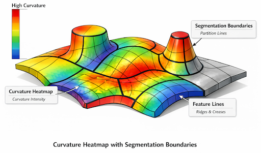
Curvature Heatmaps with Segment Boundaries

Curvature heatmaps provide visualizations of scalar fields, such as:

  • Mean curvature \( H=\frac{k_1+k_2}{2} \)
  • Gaussian curvature \( K=k_1k_2 \)
  • Principal curvature magnitudes \( \left|k_1\right|,\left|k_2\right| \)
  • Curvature gradients \( ||\nabla k_1||, ||\nabla k_2|| \)

Overlaying segment boundaries onto these heatmaps allows practitioners to ascertain whether segmentation is consistent with:

  • Curvature extrema (e.g., ridges and valleys)
  • Curvature plateaus (planar or cylindrical regions)
  • Smooth geometric transitions (blends and fillets)
  • Regions exhibiting significant curvature variation (critical in refinement strategies)

This technique is especially beneficial for analyzing freeform or organic surfaces where traditional feature lines may be subtle or non-existent.

Mesh Overlays Showing Element Alignment

As segmentation precedes meshing, visualizing mesh element alignment with segmentation boundaries provides crucial guidance regarding the quality and applicability of the segmentation. Mesh overlays clarify aspects such as:

  • Conformance of elements to curvature flow
  • Support for structured or semi-structured meshing by boundaries
  • Correspondence between refinement zones and geometric transitions
  • Reduction of distortion and skewness in mesh elements due to segmentation

Interactive applications frequently employ this visualization, enabling real-time adjustments of segmentation parameters and immediate evaluation of mesh quality.

Multi-Layer Visualizations

For intricate geometries, isolated visualization methods may prove insufficient. Multi-layer visualizations combine feature lines, curvature data, segment boundaries, and mesh overlays to furnish a comprehensive understanding of a surface’s structure and the interplay between segmentation and geometric indicators. These composite views are indispensable for diagnosing segmentation algorithm behaviors and designing advanced hybrid segmentation systems.

The Scientific Importance of Visualization

Segmentation extends beyond algorithmic computation; it demands interpretation. Visualization empowers engineers to:

  • Confirm underlying geometric premises
  • Identify algorithmic shortcomings
  • Analyze the interaction of local and global geometric signals
  • Ensure compatibility of segmentation with subsequent meshing and simulation requirements

Accordingly, visualization must be regarded as a central component of the segmentation workflow rather than a supplementary consideration.

Segmentation for Meshing

Segmentation is significant only when it directly enhances mesh generation. In contemporary computational engineering, segmentation is not merely an aesthetic subdivision of geometry; it is a structural decomposition that defines mesh behavior, element alignment, and solver performance. Effective segmentation anticipates potential challenges during meshing, while inadequate segmentation inevitably introduces complications.

Segmentation impacts meshing through several closely interrelated mechanisms.

Influence of Segmentation on Mesh Structure

Segmentation establishes the parameters under which meshing algorithms operate. Each segment functions as a domain with its unique meshing strategy, constraints, and preferred element characteristics. This enables adaptive responses to geometric diversity while preserving overall consistency.

The primary influences include:

  • Element orientation — Segments with uniform curvature facilitate alignment of elements along principal directions, thereby reducing skewness and improving numerical precision.
  • Element size control — Regions of high curvature or dense features can undergo independent refinement, distinct from flatter areas.
  • Boundary conformity — Segmentation ensures mesh boundaries adhere to feature lines, sharp edges, and functional transitions.
  • Patch-based meshing — Structured or semi‑structured meshes are achievable when segments are well defined and exhibit simple topology.
  • Transition management — Segmentation creates natural zones for seamless transitions between coarse and fine mesh regions.

These factors are integral to determining the suitability of a mesh for simulation purposes.

Strategies: Structured, Semi-Structured, and Unstructured Meshing

Distinct segments facilitate different meshing methodologies:

  • Structured meshing optimally applies to segments with uncomplicated topology and consistent curvature directions (e.g., cylinders, planes, ruled surfaces).
  • Semi-structured meshing accommodates freeform regions characterized by smoothly varying but non-uniform curvature.
  • Unstructured meshing is designated for segments exhibiting complex curvature profiles or irregular topology.

Segmentation permits these techniques to coexist within a single model without interference.

Feature-Aligned Meshing

Feature lines such as sharp edges, ridges, and valleys serve as critical constraints for the mesh. Through segmentation, these lines are incorporated as mesh edges, refinement zones, and alignment directives, preventing elements from intersecting features at arbitrary angles. This mitigates distortion and preserves solver accuracy. In regions with pronounced gradients, segmentation ensures that refinement remains localized and controlled.

Curvature‑Driven Refinement

Curvature fields dictate where finer mesh resolution is necessary to capture geometric nuances. Segmentation provides the organization required to implement curvature-based refinement smoothly, avoiding abrupt changes in element size or tangled configurations. Within each segment, refinement strategies remain coherent and consistent due to unified curvature characteristics.

Curvature-Driven Refinement

Topological Stability and Solver Efficiency

Segmentation minimizes the occurrence of inverted elements, extreme aspect ratios, poorly shaped transition zones, misaligned boundaries, and non-manifold configurations. These concerns have a direct impact on the conditioning of numerical systems. Surfaces that are properly segmented yield meshes that are easier to solve, inherently stable, and highly accurate.

Segmentation as a Meshing Agreement

Conceptually, segmentation can be viewed as a contract between geometry and the meshing process:

  • Geometry offers coherent regions with reliable behavior.
  • Meshing commits to honoring these regions and generating high-quality elements accordingly.

When segmentation is performed effectively, this agreement is fulfilled. Conversely, insufficient segmentation forces the mesher to improvise, often resulting in suboptimal outcomes.

Practical Significance

Within industrial workflows, segmentation distinguishes between:

  • Meshes that align with the intended function of the geometry
  • Meshes that consistently conflict with geometric requirements

Therefore, segmentation is not merely a preprocessing step, but a critical foundation for intelligent mesh generation.

Practical Guidelines

Effective segmentation involves more than simply applying algorithms; it requires sound engineering judgment, an awareness of geometric characteristics, and a comprehensive understanding of how segmentation choices influence subsequent meshing and simulation processes. The following guidelines distill scientific principles into practical recommendations that promote robust, mesh-ready segmentation.

Use Feature Lines as Primary Boundaries

Sharp edges, ridges, valleys, and transition zones represent discontinuities or extrema in surface differential properties. These features serve as natural boundaries for segmentation because they delineate regions with distinct curvature behaviors. Feature lines should be treated as hard constraints unless justified otherwise.

Maintain Curvature Coherence within Segments

Segments should encompass areas where curvature magnitude and direction change smoothly. Significant curvature gradients or abrupt rotations in principal directions signal the need for new segments. This approach ensures consistent element alignment and facilitates refinement within each segment.

Smooth Geometric Signals Before Segmentation

Curvature values, derivatives, and principal directions can be sensitive to noise, particularly on scanned or irregular meshes. Prior to segmentation, apply smoothing or multi-scale filtering techniques to stabilize these signals. This practice reduces spurious boundaries and enhances the reliability of curvature-based methods.

Integrate Multiple Signals for Robustness

No single geometric descriptor is universally applicable. Feature lines may be incomplete, curvature data may contain noise, and spectral cues can be overly global. By combining multiple signals—feature lines for primary boundaries, curvature for internal structure, and spectral fields for overall coherence—the segmentation process becomes more stable and meaningful.

Prefer Topologically Simple Segments

Topologically simple segments (disk-like, cylindrical, or smoothly connected) are easier to mesh using structured or semi-structured strategies. Avoid creating segments with unnecessary holes, handles, or branching boundaries unless dictated by geometry. Simpler segments yield cleaner meshes and more predictable solver outcomes.

Align Segmentation with Meshing Strategy

Segmentation should be planned in accordance with the intended mesh type:

  • Structured meshes require segments with stable curvature directions and simple topology.
  • Semi-structured meshes accommodate moderate curvature variation.
  • Unstructured meshes suit highly complex or irregular regions.

Selecting segmentation boundaries based on the meshing strategy helps prevent downstream conflicts.

Utilize Refinement Zones as Segmentation Indicators

Areas that demand high mesh density—such as tight blends, zones of high curvature, or regions containing functional details—should be isolated as separate segments. This allows targeted refinement without imposing unnecessary density across the entire surface.

Conduct Visual Validation of Segmentation

Visual inspection remains a critical step. Overlay feature lines, curvature fields, and mesh previews on the segmented surface to verify alignment between boundaries and geometric behavior. Be vigilant for:

  • Segments crossing sharp edges,
  • Abrupt curvature changes within a segment,
  • Over-segmentation in smooth regions,
  • Under-segmentation in complex regions.

Visual validation identifies issues that algorithmic methods may overlook.

Iterate Segmentation and Meshing Collaboratively

Segmentation and meshing are mutually dependent. Mathematically precise segmentation may lead to suboptimal meshes, and segmentation that facilitates meshing may require further geometric refinement. Iterative adjustments—modifying boundaries, merging, or dividing segments—lead to optimal results.

Document Segmentation Rationale

In engineering workflows, segmentation decisions impact simulation, optimization, and manufacturing. Documenting the rationale behind boundary selection, signal interpretation, and meshing strategies fosters consistency across teams and supports future revisions.

Applying these guidelines systematically transforms segmentation from a purely geometric task into a structured engineering process that anticipates meshing challenges and supports superior simulation outcomes.

Conclusion

Segmentation serves as the critical link between raw geometry and well-behaved meshes suited for numerical simulation. It partitions continuous surfaces into coherent regions, each characterized by its unique geometric attributes and meshing requirements. Leveraging differential-geometric signals—normals, curvature, curvature derivatives, and topological structure—enables the establishment of boundaries that reflect genuine surface behavior rather than arbitrary divisions.

Various segmentation techniques emphasize different aspects of geometry. Feature-line methods capture sharp transitions and essential edges; curvature-based approaches highlight smooth variation and intricate shapes; spectral and graph-based methods reveal global organization and bolster robustness. In practice, reliable systems combine these methodologies, utilizing each according to its strengths.

Segmentation fundamentally shapes the resulting mesh, affecting element orientation, refinement patterns, boundary conformity, and the feasibility of structured or semi-structured meshing. Proper segmentation yields meshes aligned with curvature flow, respects geometric features, and minimizes distortion. Conversely, inadequate segmentation can introduce compromises, leading to solver instabilities and reduced accuracy.

The outlined guidelines—including respecting feature lines, smoothing signals, integrating multiple cues, validating visually, and iterating alongside meshing—advance segmentation from theoretical exploration to practical engineering workflow. They ensure that segmentation is both mathematically rigorous and attuned to the complexities of simulation, manufacturing, and design intent.

As geometrical complexity increases, segmentation's importance grows. It acts as the organizing principle that allows meshing algorithms to scale, adapt, and remain robust. With a deep understanding of segmentation techniques, engineers can guide the meshing process effectively, unlocking high-quality simulations across diverse applications.
Download PDF